Don’t Skip the Knowledge Popularization About Portal Steel Frame Industrial Buildings
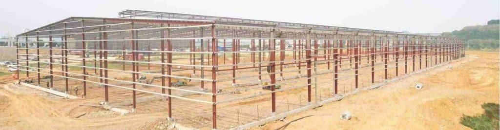
Generally speaking, a portal steel frame industrial building is an industrial building with a steel structure as its main load-bearing system. Its design core lies in using the portal steel frame as the main load-bearing support—shaped like daily doors, it is simple yet stable enough to bear the building’s main structure weight. It is also a common lightweight type, with main load-bearing components including steel beams and steel columns, presenting an overall “door”-shaped layout that typifies portal steel frame industrial buildings.
The structural form of portal steel frame industrial buildings can be flexibly adjusted to actual needs. Specifically, lightweight portal steel frame industrial buildings are ideal for steel workshop buildings without production cranes, while heavy-duty ones are a must for those needing cranes to transport heavy materials/equipment. In terms of layout, they offer single-span, double-span, and multi-span options, and can be equipped with eaves overhangs, annexes, or even upgraded to multi-story steel buildings as per project requirements. Personalized modifications (e.g., rain-proof eaves overhangs, small auxiliary annexes) can also be tailored for them.

These advantages make portal steel frame industrial buildings well-suited to the construction industry’s needs. Without excessive supporting columns, they avoid obstruction when placing factory equipment, storing warehouse goods, or facilitating workers’ operations. Moreover, their key components can be prefabricated in factories and assembled on-site—this not only shortens the construction cycle of portal steel frame industrial buildings but also ensures consistent quality. They also have strong wind, snow, and earthquake resistance, ensuring long-term stability.
Nowadays, portal steel frame industrial buildings are not only the first choice for factory workshops and large storage sites but also reliable for commercial venues and cultural & entertainment facilities. In fact, all projects needing open internal space prioritize prefabricated portal steel frame industrial buildings, as they balance functionality, efficiency, and durability—key reasons for their popularity in modern construction.
Easily Understand the Components and Structural Details of Portal Steel Frame Industrial Buildings
In the main structural components of portal steel frame industrial buildings, columns and roof beams can be designed as solid-web H-shaped or lattice members. To reduce steel consumption, these members may also adopt a variable cross-section based on the bending moment diagram distribution. While solid-web members use slightly more steel, they are easy to fabricate and widely applied in practical projects of portal steel frame industrial buildings.
For the secondary structure of portal steel frame industrial buildings, cold-formed thin-walled steel is preferred for roof purlins and wall girts; if the plant’s column spacing exceeds 12m, truss-type purlins are more economical. As flexural members, the secondary structure connects to the main rigid frame via bolts—it bears loads from the enclosure system, transfers them to the main structure, and provides lateral support to enhance the main structure’s overall stability in portal steel frame industrial buildings.
The core of the enclosure system for portal steel frame industrial buildings is cladding panels, which are usually made of roll-formed thin metal sheets or other lightweight composite materials. These panels are connected to the secondary structure through specific methods to bear external loads such as wind, snow, and construction loads. It is worth noting that cladding panels are not only supported by the secondary structure but also can provide lateral support for the secondary structure, enhancing the stability of the secondary structure to a certain extent.
Moreover, after the cladding panels are connected to the secondary structure, they form strong shear stiffness in their own plane—a phenomenon commonly known as the “diaphragm effect.” This effect enables the plane-loaded portal steel frame industrial buildings to have certain spatial structural performance.

In addition, roof bracings and inter-column bracings of portal steel frame industrial buildings are usually designed as tension members, with tightened cross-round steel bracings being the preferred choice. If the structure includes cranes with a capacity of over 5 tons, the inter-column bracings must be replaced with angle steel or other section steel bracings. For the inter-column bracings in the mezzanine structure part of portal steel frame industrial buildings, angle steel or other section steel bracings should also be selected.
According to the actual architectural requirements, portal steel frame elements of different sizes can be arranged and combined to form a variety of structural forms, which meet the usage needs of various single-story buildings. Common forms include those with partial mezzanines, with ventilators or parapets, with lean-tos, and with eaves overhangs. They can also be designed as single-slope, multi-span with single ridge and double slopes, multi-span with multiple ridges and multiple slopes, and combined high and low spans. In addition, frame-type portal steel frames are also used in some scenarios.
▪ Basic Forms of Portal Steel Frame Buildings
▪ Local Second-Story Joints Refer to Multi-Story Frame Systems


In the derivative structural forms of portal steel frames, crane equipment can also be flexibly arranged according to actual needs, and partial second-floor spaces can be added at the same time.
Essentially, gable portal frames also belong to the category of multi-span portal frames; the main difference lies in their intermediate columns, whose section orientation is rotated by 90 degrees compared with that of conventional portal frame columns.
Steel Selection for Portal Steel Frame Industrial Buildings Based on Standards and Common Grades
The steel selection for portal frame industrial buildings shall be based on the Chinese national standards Code for Design of Steel Structures (GB 50017) and Technical Specification for Steel Structures of Light-weight Portal Frame Buildings (GB 51022). The commonly used steel grades and their application scenarios are as follows:
Q235 steel, as the most commonly used and economical choice, has a yield strength of 235N/mm² and possesses good strength, ductility, and weldability. It meets the requirements of most portal frame buildings without cranes or with small-tonnage cranes; it is not only the preferred material for main frames (beams, columns) but also the steel usually used for secondary structures (purlins, wall girts);
Q355 steel (formerly designated as Q345) is suitable for more critical components, with a yield strength of 355N/mm². Its strength is approximately 36% higher than that of Q235 steel. When the structure has a large span, heavy load (such as with large-tonnage cranes), or large column spacing, the use of Q355 steel can effectively reduce the cross-sectional size of components and save steel consumption. Although its unit price is slightly higher, it offers better overall economy, and is often used for main frames (beams, columns) subject to large loads.
Higher-strength steels such as Q390, Q420, and Q460 are rarely used in portal frames and are only considered in super large projects with special heavy-duty cranes or extreme load conditions. Overall, Q235B or Q355B is commonly used for main frames (beams, columns), while Q235 steel is usually adopted for secondary structures (purlins, wall girts).

Practical Layout Principles for Portal Steel Frame Industrial Buildings
The layout of Portal Steel Frame Industrial Buildings follows a systematic planning logic, focusing on lateral rigid frames, longitudinal bracing, enclosure systems, and secondary structures. The details are as follows:
- Lateral Rigid Frame Layout (Main Lateral Force-Resisting System): As the “skeleton” of portal steel frame industrial buildings, lateral rigid frames bear all vertical loads and lateral loads. For spans, they should be determined based on process requirements such as production line width, equipment layout, and logistics passages. The common economic span ranges from 18m to 36m; larger spans (e.g., over 45m) are technically feasible but require economic comparison—sometimes using trusses or brackets is more cost-effective. Lateral rigid frames can be arranged as single-span, double-span, or multi-span. In multi-span layouts, intermediate columns usually adopt the form of pin-ended columns, which are hinged to beams to simplify construction and save materials. Column spacing (i.e., the distance between rigid frames) is a key factor affecting steel consumption and economy; the common economic column spacing is 6m to 9m, and 7.5m or 8m is widely used in scenarios without cranes or with small-tonnage cranes. Increasing column spacing (e.g., to 12m) will significantly increase steel consumption for rigid frame beams and crane beams, but it reduces the number of rigid frames and foundations—comprehensive trade-offs are needed, and steel consumption for purlins and wall girts will also increase accordingly. Eave height is determined by service clearance, crane rail top height, and roof structure height; the roof slope is usually 5% to 10% (approximately 1/20 to 1/10)—too small a slope is unfavorable for drainage, while too large a slope increases building volume and steel consumption.
- Longitudinal Bracing System Layout (Ensuring Overall Stability): The longitudinal bracing system acts as the “ligaments” of portal steel frame industrial buildings, connecting individual lateral rigid frames into a stable spatial whole to resist longitudinal loads (such as longitudinal wind loads, seismic forces, and longitudinal crane braking forces) and ensure stability during installation. Regarding layout positions, roof horizontal bracing is usually arranged in the end bays (first or second) and the middle bays of temperature sections at certain intervals (e.g., ≤60m); for long workshops, temperature expansion joints must be set, with bracing installed on both sides of the joints. Inter-column bracing should be arranged in the same bays as the roof horizontal bracing to form a strong lateral force-resisting truss system, transferring loads to the foundation. For layout forms, cross round steel (tightened with turnbuckles) or angle steel cross forms are usually used—round steel bracing is lightweight and economical, only bearing tension (designed as tension members), making it the most common form. When cross bracing cannot be installed at locations with large door openings or passages, portal bracing can be used instead. Its core functions include providing out-of-plane support points for rigid frame columns to reduce their effective length, transferring and resisting longitudinal horizontal forces, and ensuring the overall stability of the structure during installation.
- Enclosure System and Secondary Structure Layout: The layout spacing of purlins and wall girts in portal steel frame buildings is mainly determined by the strength and stiffness of roof panels and wall panels, with a common spacing of 1.5m. To reduce the out-of-plane effective length of purlins and wall girts and improve load-bearing capacity, a tie rod and strut system (usually made of round steel) should be installed to form a stable force-bearing system. Wind columns are arranged at gables to bear wind loads transmitted by gable wall panels; their top ends are hinged to rigid frame beams via end plates, enabling the transfer of both horizontal and vertical forces.
- Summary Core Layout Process: The core layout process of portal steel frame buildings follows the logic of “demand-oriented → preliminary planning → systematic layout → calculation and optimization”. Firstly, determine the span, height, crane tonnage, and door positions based on process requirements; then initially confirm the economically reasonable column spacing (e.g., 7.5m) and roof slope (e.g., 1/10); next, arrange lateral rigid frames to form the main load-bearing system; then install longitudinal bracing, setting roof bracing and inter-column bracing in end bays and the middle of temperature sections to build a stable spatial structure; subsequently, reasonably arrange secondary structures such as purlins, wall girts, and their tie rod systems; finally, set up the gable system and arrange wind columns. Ultimately, all layouts must be modeled, calculated, and optimized using structural calculation software (such as PKPM, YJK) to ensure that all layout principles are met.

Design Points for Portal Steel Frame Industrial Buildings: Seismic Resistance & Fire Protection
When designing portal steel frame industrial buildings for seismic resistance, the first thing to focus on is the rationality of the overall layout: the mass and stiffness of the workshop structure must be evenly distributed. This ensures the workshop bears force uniformly and deforms coordinately under seismic action, minimizing the risk of local overloading and subsequent structural damage caused by uneven stiffness. For the transverse structural design, rigid frames are more suitable, or frames where the roof truss and columns form a certain degree of consolidation—this design fully leverages the load-bearing performance of the steel structure, reduces transverse structural deformation, and further enhances seismic capacity.
It is particularly important to note that most damage to portal steel frame industrial workshops is caused by member instability rather than insufficient member strength. Therefore, the reasonable arrangement of the bracing system is crucial: scientific placement of components such as inter-column bracing and roof truss horizontal bracing can effectively ensure the overall stability of the workshop structure and prevent member instability under seismic action. Additionally, the design of structural connection nodes must be strictly controlled—it is essential to ensure that nodes do not fail before the full cross-section of structural members, allowing the members to enter a plastic working state and fully absorb seismic energy, thereby maximizing the building’s seismic resistance.


Core Advantages of Portal Steel Frame Industrial Buildings: Efficiency, Self-Weight & Space Adaptability
The popularity of portal steel frame industrial buildings in the industrial sector stems from their practical advantages in multiple aspects. Starting with construction efficiency, the steel structural components of these buildings can be mass-produced in factories, eliminating the need for complex on-site pouring work; once transported to the construction site, the building can be completed just by assembling the components. The entire process is simple and efficient, significantly shortening the project’s construction cycle and helping enterprises start production faster.
In terms of building self-weight, the advantage of portal steel frame industrial buildings is even more notable: it can reduce the structural mass of the building by approximately 30%. This feature is particularly critical in two scenarios—one is areas with low foundation bearing capacity, where the lighter self-weight reduces pressure on the foundation and lowers the cost of foundation reinforcement; the other is areas with high seismic fortification intensity, where the lighter structure reduces inertial force under seismic action, resulting in much better comprehensive economy compared to traditional reinforced concrete structural systems.
When it comes to space utilization and functional adaptability, portal steel frame industrial buildings also perform well. Their economical span typically ranges from 24 to 30 meters, providing ample space for operations and meeting the large-space needs of various industrial activities such as mechanical processing and logistics storage; at the same time, the structural design offers high flexibility. Enterprises can adjust the structure into multi-story or multi-span configurations based on their actual production needs, and even install special industrial equipment like cranes, fully adapting to the production scenarios of different industries.
Fire Protection Design: Address the Heat Resistance Shortcoming of Steel & Avoid Collapse Risk

Portal steel frame industrial buildings have a notable weakness: the poor fire resistance of their steel structures. Once the temperature of steel exceeds 100℃, its performance gradually changes as the temperature rises: tensile strength decreases continuously, while plasticity increases; when the temperature reaches 500℃, the steel’s strength drops to an extremely low level, unable to support the building’s weight, which may eventually lead to the collapse of the steel structure.
Therefore, design codes clearly stipulate that if the surface temperature of the steel structure may be in an environment above 150℃, thermal insulation and fire protection measures must be taken. Currently, the most commonly used solution in the industry is to apply heat-resistant coatings to the surface of the steel structure—these coatings form a thermal insulation layer in high-temperature environments, slowing down the rate of steel temperature rise, buying time for fire rescue, and protecting the steel’s performance from rapid degradation, effectively avoiding the risk of building collapse.
About Author: K-HOME
K-home Steel Structure Co., Ltd covers an area of 120,000 square meters. We are engaged in the design, project budget, fabrication, and installation of PEB steel structures and sandwich panels with second-grade general contracting qualifications. Our products cover light steel structures, PEB buildings, low-cost prefab houses, container houses, C/Z steel, various models of color steel plate, PU sandwich panels, eps sandwich panels, rock wool sandwich panels, cold room panels, purification plates, and other construction materials.